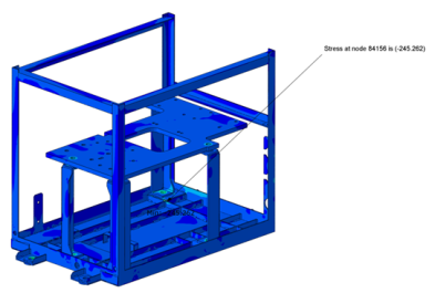
This analysis was to a client company, which is an OEM of Frames. The needs were to create an FE model for performing static analysis of the frame structure and to perform the Fatigue Life Assessment of the welded location in the structure.
Pic: Nominal stress contour plot of the frame
The key complexities faced by our engineers were while performing the fatigue life assessment as when the word ‘life-assessment’ comes, yes, there will be complexities!
Creating a fine FE sub-model was a challenge by itself. Identifying the hot spot [1] location of the weld was another challenging task, which indeed needed hours of peaceful research. The greatest challenge was faced when performing the extraction of high nominal stress of the hot spot location, in order to perform the fatigue life assessment of the weld location.
 Pic: Sub model of the weld spot
Was it overcome?
Yeah! By running the sub-modelling [2] analysis for the weld location.
Coming to the solution, we applied the Boundary conditions, loading and stress results from the global model to the sub model. The maximum stresses were observed at the root of weld. Membrane stress and the bending stress values were extracted at the weld root region to obtain the nominal stress values for the same region. Fatigue life assessment was done by using the nominal stress value extracted at the weld root.
 Pic: Sub model Boundary condition
The customer in turn saved a lot of experimental cost by simulating it prior to experimentation as it would have taken days together. Also, a large chunk of the cost, time and material were reduced to a great extent. There will always be induced errors during testing, some due to variation in the manpower and testing induced errors. Such errors were also predicted and reduced.
 Pic: Stress contour model of the sub model
[1] Hot spot- region/zone where the temperature is high(exceeding the limit).
[2] Sub modeling is a finite element technique used to get more accurate results in a region of your model. Often in finite element analysis, the finite element mesh may be too coarse to produce satisfactory results in a region of interest, such as a stress concentration region in a stress analysis. The results away from this region, however, may be adequate.
To obtain more accurate results in such a region, you have two options: (a) reanalyze the entire model with greater mesh refinement, or (b) generate an independent, more finely meshed model of only the region of interest and analyze it. Obviously, option (a) can be time-consuming and costly (depending on the size of the overall model). Option (b) is the sub modeling technique.

